
往复式压缩机状态监测in oil and gas
的oil & gas industry has continuously increased its requirements, together with the high complexity of technological systems and the higher competitiveness of markets, it has compelled end-users to implement adequate maintenance strategies for these systems to improve plant availability and productivity to meet those more demanding criteria.
Normally when operating rotating equipment, different maintenance strategies are applied. The simplest method is torun a machine until it stops due to a failuretaking the risk that comparably small damage can cause expensive consequential damages. When wear mechanisms within the machine are well understood and the timely progress of wear is identified, worn parts should be replaced before their lifetime is reached to maximize use of their wear potential and prevent component failures (preventive maintenance). However, the lifetime of components for reciprocating compressors, such asvalves and bearings, are not subject to linear wear which makes it difficult to decide on the best time to replace a component based on operating hours. Maintenance decisions on components that are experiencing non-linear wear-out are challenging and cannot be made by relying solely on a time-based strategy. They requirecontinuous monitoringof certain parameters that allow judgment of the components’ condition and an estimation of the best time for a replacement. This is known aspredictive maintenance.
Since the 70s, many oil and gas plants have been built with a large fleet of reciprocating compressors installed. Reciprocating compressors did not get the high-priority monitoring given to centrifugal machines. The reasons why are partially based on the higher number of centrifugal and axial machines in comparison to reciprocating compressors and operators just did not encounter severe damages due to the lower kinetic energy of these relatively slow-running machines. Recently, however,reciprocating compressors are having more failures while being process-critical at the same time.
At all times, operators, engineering procurement and construction companies (EPCs), and original equipment manufacturers (OEMs) have followed the existing applicable guidelines and standards during the final engineering stage. Those standards were effective at the time of construction, and to a large extent are still valid today. However, upon studying the age of the reciprocating compressor population, one will recognize that, in many cases, these large, critical machines have never been replaced and they have been in operation since their initial startup date many decades ago. To understand why, even after several catastrophic failures,we still find inadequatemachinery protectionand monitoring on most of these machines, a review into the history of applicable standards can help to lift the fog.
From the first edition of API 670 published in 1976 to the fourth edition in 2000, the API 670 only focused on the technical requirements of centrifugal and axial compressors. In November 2014 the API 670 5th edition was released with special guidelines around the monitoring and protection of reciprocating compressors. Therefore,there is an emergent need now for new and existing compressors in the plant to comply with the API 670 5th edition requirementsand fill the gap to increase availability, detectability, and monitoring of these types of compressors.
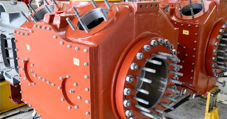
Reciprocating compressors areone of the most critical asset(s) in the plant; these types of machines can provide higher compression ratios than similar axial or centrifugal compressors.
Reciprocating compressors have an essential role in many industrial processes and in many industries such as oil and gas production, refining, enhanced oil recovery, corrosive gas production, low temperature, and cryogenic applications. Specific examples include:
- Reciprocating compressorupstream: for exploration, gas lift, reinjection and gas plant
- Reciprocating compressors inmidstreamfor gas gathering, reinjection, boosting and transmission, storage and LNG.
- Reciprocating compressors fordownstreamrefinery and petrochemicals, hydrocarbon processing, hydrocracking hydro-treating fractionating, fertilizers (ammonia, urea), and low-density polyethylene (LDPE).
- Natural gas applicationsare generally part of the upstream/midstream, wellhead gas gathering, vapor recovery, gas re-injection, gas lift, pipeline gas transmission, gas storage, fuel gas boosting, and boil-off gas are all part of the natural gas process.
Reciprocating compressors in these services mentioned above have different characteristicssuch as unique materials of construction, lubrication system design, driver unit type, capacity control system, and process characteristics. It is in the downstream segment that there is more interest in condition monitoring solutions. In these processes, profit links directly to reciprocating compressor availability.In these processes, plants often categorize reciprocating compressors as critical machines.
Compressors designed for service in refineries aretypically built to theAPI-618 standard. Refineries use reciprocating compressors primarily for two services:
- In a hydrocracker unit, process gas hydrogen is used, which, being a low molecular weight gas,can only be compressed more efficiently by a reciprocating compressor.
- In flare gas and vapor recovery services which must handle a wide variety of molecular weights,a reciprocating compressor can perform better compared to centrifugal compressors.
Typically, synchronous motors drive these compressors. ISO 13631 standards describe the basic design and operating features for relatively high-speed compressors that will provide service in the upstream and midstream segments. There isa wide variety of applicationhere including:
- gas gathering (variable ratio and gas composition)
- gas re-injection (high ratio and low flow)
- gas lift (high ratio and low flow)
- pipeline gas transmission (variable flow capability)
- storage (variable flow capability)
- fuel boosting (high compression ratio and low flow)
的se compressors may be coupled to reciprocating natural gas engines or electric motors as prime movers.
In spite of the criticality and importance of the reciprocating compressors, they are sometimes unobserved by condition monitoring specialists.的PDM tool (FFT portable vibration analyzer) which is routinely used on rotating equipment is not well suited for reciprocating machines and has been unsuccessfully monitoring the reciprocating compressor for many years. Therefore, theoverall machine health is frequently ignoredand not diagnosed correctlyuntil damage occurs and it becomes too lateto save the machine from failure.

Aportable vibration analyzeris useful for the typical balance of plant non-critical machines with a generally long time between failures and on-line monitors which are used for protection and condition monitoring and are most beneficial for critical machines and units with a short point-to-failure time frame.这些传统的振动分析是合适的for early fault detectionof rotating (centrifugal and axial) machines with some limitation in reciprocating compressors due to the following:
- Reciprocating machinesgenerate uneven forces, and normally theprocess is intermittent, therefore the overall vibration amplitude is relatively unaffected and provides little warning of serious faults while serious damage may exist.
- 的impact caused by mechanical looseness producesvery short duration waves and high amplitude spikeswhich need continuous monitoring (online system) on crossheads for early detection.
- Common valves problems such assticky valves(delayed opening impact) andlost valve springs (earlier opening impacts) need a crank angle tracking system for fault detection.
When comparing the working principle of a reciprocating compressor with a centrifugal machine, it becomes apparent thatreciprocating compressors require a more dedicated monitoring approachdesigned to handle all the special challenges reciprocating compressors bear.
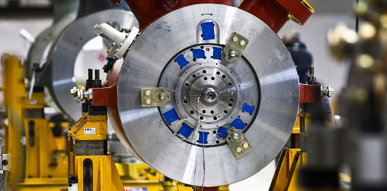
的normal operation of the reciprocating compressor shows a very different behavior;pistons are driven back and forth by a crosshead drive train involving reversal of piston rod forces from tension to compression and vice versa, making the entire frame with all its components shake and bend to a good degree; suction and discharge valves create an opening and closing impacts creating vibration throughout the entire machine. Looking at the operation of reciprocating machines,the crosshead is clearly the focal point, the rotating movement of the crankshaft is transformed into a reciprocating (linear) movement of the piston rod. It’s the central component where all major forces are transferred via a sophisticated crosshead to the piston rod.
Reciprocating forces are typically much larger than any rotational forces associated directly with the crankshaft (misalignment, rubs, unbalance, etc.). These reciprocating forces are transmitted through the piston rod. Equal and opposite reaction forces are transmitted through the distance piece back to the frame. When we evaluate all the components that transmit the reciprocating forces in the compressor, it turns out thatthe crosshead pin tends to be the weakest link.
Forces on the crosshead pin are affected by the following:
Gas Load:
Force on the piston rod caused by the pressure of gas against the faces of the piston changes as chambers are loaded and unloaded. Because of the piston rod, the crank end of the piston has a smaller surface area than the opposite head end for the gas to push against. If the gas pressure is the same in both chambers, there will be a net force pushing the piston toward the crankshaft.的combination of the pressure force from each chamber produces a complex waveform.
Inertial Load:
This force on the piston rod caused only by the acceleration of the reciprocating components (piston, piston rod, and crosshead) of the throw.的inertial mass for nearly all reciprocating compressor condition monitoring installations includes the crosshead assembly, crosshead nut, piston rod, and piston assembly.This collection of mass for inertia is consistent with the definition provided in API-618 5th edition.
Combined Load:
Combined Load is defined as force on the piston rod caused by the combination of gas force and inertial force.This force varies continuously throughout the revolution.的term appeared in both the 4th and 5th edition of API-618 with the same definition; however, the 4th edition required that it be calculated every 10 degrees and the 5th edition required that it be calculated every 5 degrees.
Reciprocating & Rotating Masses Unbalance Forces:
的se forces are predominant at 1X and 2X compressor speed and arecaused by asymmetrical crankshaft design and imperfect manufacturing tolerances. They are usually much smaller than inertial and gas load forces.
Gas Unbalance Force:
的se arecaused by pressure in the pulsation bottles and pulsation at the cylinder nozzle area and in piping. Allowable pulsation levels are defined in API-618. Although these pulsating forces are usually much smaller than the forces listed above,they can be destructive to piping and piping support systems if they happen to correspond to resonant frequenciesfor the structures’ failure modes of the reciprocating compressor.
- Abrasive particlescan be especially harmful when they enter the cylinder and accelerate rider band wear. As they pass through the cylinder valves they can damage springs, sealing elements, and valve seats.
- Coke depositsare formed when high temperatures cause cylinder lubricating oil to decompose. Lighter hydrocarbon molecules are driven off and solid carbon deposits are left behind. These hard deposits can interfere with the proper action of valves, piston rings, and rider bands.
- Corrosive substancescan produce corrosion that prevents proper sealing of piston rings, piston rod pressure packing, and valves, and can even cause complete failure if the components break apart.
- Liquid slugscan be harmful to valves, pressure packing, and piston rings since liquids are essentially non-compressible. Liquid may come from incomplete separation in some chemical processes, and from condensation in interstage coolers or cold stages of the process. This is a catastrophic condition for running gear and tends to break within a couple of cycles.
- Process gas polymerization: small “unsaturated” molecules (with double or triple bonds between carbon atoms) in the process gas can combine to form long polymer chains, which can foul cylinders, pistons, and valves.
- Crankshaft bearingsexcess clearance caused by inadequate lubrication, wear, and overloading results in elevated frame vibration.
的se are just some of the components that are susceptible to abnormal motion when undesirable conditions exist.Normal component wear is a large contributor to excessive clearance, so abnormal component motion may be expected to become more severe over time.
由于异常运动导致糟糕的性能nce and accelerated wear of the components, there can often be an increased rate of wear once the components have started to degrade.This affects the slope of the P-F curve as time goes by.
High maintenance costs are associated with reciprocating compressors attributed to various compressor components (valves ranked highest); however,outage costs can easily exceed the maintenance coststo replace a valve. While a valve in an early stage of failure may not have a significant effect on the machine condition, advanced valve failure can lead to excessive loading and machine wear.With an advanced compressor monitoring system, it is possible to evaluate possible safety concerns, to assess the effect of the valve leak on machine condition, and to make an economic evaluation of the cost of operating with faulty components.

Although trending of overall vibration measurements is an excellent tool for monitoring the health of rotating machinery, it is not generally effective for monitoring reciprocating machinery because common faults present themselves as impacts with little effect on overall vibration levels. As a result, abnormalities are not diagnosed until damage has occurred and it is too late to take simple corrective measures.的re are several reciprocating machinery faults which do not significantly increase a machine’s overall vibration level until damage has reached a severe level.
的reason is that many typical faults on reciprocating machinery are characterized by mechanical looseness, which results in impacting or shock events in the machine. Since impacts generally have little effect on the overall vibration level, these faults are not detected at an early stage. As a result, abnormalities are not diagnosed until damage has occurred and it is too late to take simple corrective action(s).
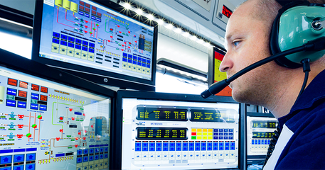
的main intent of installing anonline monitoring and protection systemis to ensuresafety of personnel, assets, and environment.It also provides critical data that operators
and engineers can use to assess equipment condition, determine machine availability, and make informed run/no run decisions.In some cases, this data may also be used to maximize operating efficiency and machine health.
Common compressor problems produce recognizable vibration symptoms.通过使用适当的监测技术,我们可以gain a much better understanding of the compressor condition.
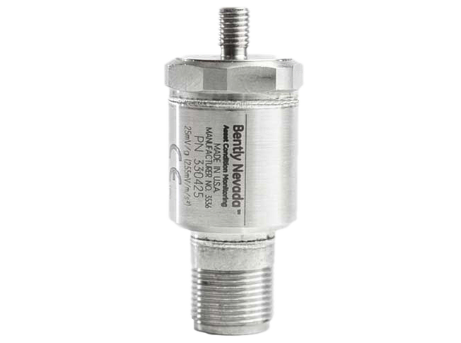
In reciprocating machinery,accelerometers, due to their higher frequency response characteristics, should be used to measure impact and gas leak malfunctions that have characteristically high-frequency signals. Velocity transducers, with their lower frequency response characteristics, are intended to measure rotational related malfunctions, such as overloading, foundation degradation, or unbalanced forces.的two transducer types work together to give a reasonable picture of the machine condition.
的se measurements can be useful for evaluating forces caused by piston rod loading (gas and inertial forces), and moment forces imparted to the main bearings by the crankshaft because of its asymmetric design.Velocity sensors can be installed on the frame to measure overall machine vibration.Recommended transducer locations are aligned with frame webs to efficiently capture the transmitted vibration from the main bearings. The magnitude for a frame velocity signal is usually low (less than 0.3 ips). However, at low frequencies, even small amplitudes of measured velocity correspond to large amounts of displacement.
的se measurements can be used to detect load reversal and valve events.Acceleration sensors are recommended to be installed on each crosshead to monitor compressor impulse events.Proper surface preparation is critical for accurate vibration measurements.
As parts wear over time, mechanical clearances increase.This extra clearance gives the parts more distance to gain velocityand the impacts between the components become more energetic.
的se mechanical impacts produce high-frequency structural vibration. The frequency band of3Hz-2kHz depicts mechanical loosenessand this signal is used for protection. Higher frequency components up to 30kHz carry the energy of impacts from valve operation and gas leaks and this unfiltered waveform is used to capture malfunctions mainly related to valves.
This vibration measurement deals with valve operation and movement, acoustic effects, and the analysis of various leak scenarios.Acceleration sensors can be installed on the cylinder to detect impulse events associated with the compressor cylinder valves.It is especially important to ensure that recommended sensor mounting practices are used for accelerometers.
A traditional phase reference signal (used for vibration analysis) is triggered by a detectable feature that provides one signal pulse per rotation of the machine rotor shaft.Sensors that are commonly used for this purpose include eddy current displacement, inductive (magnetic), and optical transducers.
的reciprocating machine crank angle signalshould be triggered by a specially-designed multi-event wheel. This wheel incorporates a once-per-turn reference pulse (triggered by the double notch developed by the indexing tooth) along with multiple synchronizing pulses that allow correcting the crank angle measurement for torsional error during every rotation of the crankshaft.
的multiple notches on the special recip multi-event wheel allow the data collection process to be re-synchronized 12 times per crank rotation (every 30 degrees).的divided notch is used to identify the TDC location of the primary reference throw.
Correlating different measurements referenced to crank angle allows a more thorough diagnosis of observed symptoms.
Both the rider bands and the piston rings contact the cylinder liner. However, the rider bands are designed to carry the full weight of the piston while the piston rings are designed only to provide sealing between the piston and bore. The piston rings and their mounting grooves are purposely designed with clearance to allow the rings to “float”, without carrying any of the vertical load of the piston’s weight.的rider bands are intentionally designed to seat fully within their mounting grooves so that they can support the piston’s weight.
Rider bands are designed to slowly wear away over time.In good operating conditions, the rate of wear can be very low, especially in lubricated-cylinder applications.However, adverse conditions such as improper cylinder lubrication, component misalignment, or abrasive particles or moisture in the process gas can increase the wear rate.
This measurement focuses on the DC voltage signal from the proximity probes and calculates a displacement value inside the cylinder using the principle of similar triangles.Trending this displacement measurement allows one to get an indication of potential rider band wear over time.的re are some operating conditions that may make the rod drop measurement unreliable, so care must be taken before applying this monitoring method.
It is important that theproximity probeis calibrated for the actual piston rod that it will be measuring.的standard scale factor for typical proximitor probe systems will be affected by several factors in the complete system.Factors include the composition of the piston rod casting alloy, surface treatments, coatings, or contamination, and the roundness of the cylindrical rod itself.
的main purpose of a rod position monitor isto constantly measure both the vertical and horizontal position of the piston rod during compressor operationand to monitor rod flexing in both axes.
Knowing the crosshead clearance and the maximum movement expected at the piston, we can find the maximum displacement expected at the pressure packing case proximity probe, and we cancreate alarm setpointsaccordingly. The probe position changes continuously as the piston travels through its stroke.Peak to peak vibration levels in both planes can provide indications of potential problemssuch as impending piston rod break or piston rod damage from rubbing on pressure packings.
Advancements in technology and enhancements in industry standards and best practices encourage top management tostart investing in close monitoring of their existing reciprocating compressors by implementing these new monitoring techniqueswhich are available now after calculating the benefits and ROI on machine uptime and reliability.
Start asking your condition monitoring and reliability teams if they are confident enough with their current existing systemsfor monitoring reciprocating compressors as they are the same towards centrifugal ones, andyou might be shocked that your recips are not protected and monitored well.
If you would like tolearn more about how Bently Nevada can help you get the most accurate, actionable, real-world insights into your reciprocating compressors- in fact all of your machinery assets - pleasecontactusand we will be happy to assist you in updating your condition monitoring strategies.
Keywords:asset reliability, best practice, PDM, failure modes, equipment reliability, proactive maintenance, critical equipment, critical, availability, condition monitoring, maintenance strategy.
- Steven M. Schultheis, Charles A. Lickteig, and Robert Parchewsky,“Reciprocating Compressor Condition Monitoring”, 2007, Proceedings of the 36th Turbomachinery Symposium
- Bryan R. Long, Ph.D., P. Eng., and David N. Schuh, P. Eng.,“Fault Detection and Diagnosis in Reciprocating Machinery”, provided by a machinery consultant company - Beta Machinery Analysis.
- European Forum for Reciprocating Compressors,“Guidelines for Vibrations in Reciprocating Compressor Systems”, Third Edition – May 2012.
- G. Zusman, J. Palm.“Impact Measurement for Reciprocating Compressors”Vibration Institute 26th Annual Meeting (June 18-20, 2002).
- “Reciprocating Compressor Operation and Maintenance”, Heinz P. Bloch & John J. Hoefner
- API 670 5th editionNovember 2014 (Machinery Protection Systems) Annex P.
- API 618 5th editionReciprocating Compressors for Petroleum, Chemical, and Gas Industry Services.
- Compressor Handbook(McGraw-Hill Handbooks) 1st Edition by Paul Hanlon (Author)
- Troubleshooting Rotating Machinery: Including Centrifugal Pumps and Compressors, Reciprocating Pumps and Compressors, Fans, Steam Turbines, Electric Motors, and More1st Edition
Bently Nevada’s product line has beensynonymous with machinery protection and condition monitoring for more than 60 years. Our network of global experts is dedicated to helping our customers solve some of their toughest challenges in the oil and gas and power generation industries. From refineries and petrochemical plants to hydroelectric facilities and wind farms,本特利内华达资产状态监测提供了trusted and proven vibration monitoring equipment and a comprehensive services portfolioto help improve the reliability and performance of production assets like turbines, compressors, motors, generators, and everything in between.
Behind every suite of great products isa team of great people, and the Bently Nevada team isone of the most experienced in the industry. That experience translates into high-quality, flexible, and scalable solutions coupled with a dedicated services team focused on providing proactive, consistent support throughout the lifecycle of your operations.Our domain experts can help you operate safely while maximizing plant uptime and efficiency.
Copyright 2019 Baker Hughes Company. All rights reserved. Baker Hughes provides this information on an “as is” basis for general information purposes. Baker Hughes does not make any representation as to the accuracy or completeness of the information and makes no warranties of any kind, specific, implied or oral, to the fullest extent permissible by law, including those of merchantability and fitness for a particular purpose or use. Baker Hughes hereby disclaims any and all liability for any direct, indirect, consequential or special damages, claims for lost profits, or third party claims arising from the use of the information, whether a claim is asserted in contract, tort, or otherwise. Baker Hughes reserves the right to make changes in specifications and features shown herein, or discontinue the product described at any time without notice or obligation. Contact your Baker Hughes representative for the most current information. The Baker Hughes logo, the Bently Nevada logo, and System 1 are trademarks of Baker Hughes Company.
Our Experts

Stephen Plaisance
Machinery Diagnostics Services Technical Leader
BIO
Stephen Plaisance, PE, Machinery Diagnostics Services Technical Leader for Reciprocating Compressors in North America and responsible for the successful commissioning of condition monitoring solutions on reciprocating compressors across the globe.