
Reciprocating Compressor Condition Monitoring
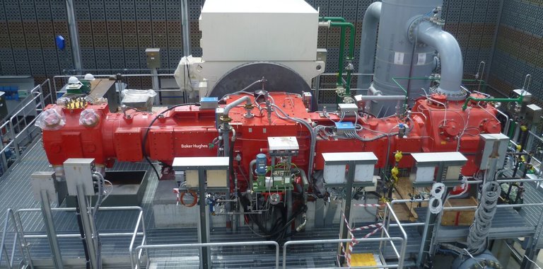
Rider Band Wear Monitoring on Reciprocating Compressors – A Case Study on Sour Gas Application

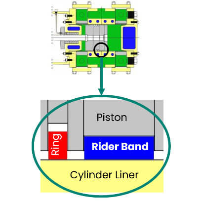
骑手乐队(也称为穿带)是一个惩罚学生rtant consumable component on horizontal reciprocating compressors based on which operators plan maintenance outage. Although both the rider bands and the piston rings contact the cylinder liner; however, the rider bands are designed to carry the full weight of the piston while the piston rings are designed to provide sealing between the piston and bore. The piston rings and their mounting grooves are purposely designed with clearance to allow the rings to "float", without carrying any of the vertical load of the piston's weight. The rider bands are intentionally designed to seat fully within their mounting grooves, so that they can support the piston's weight.
Historically, rider bands were made from soft metals such as babbitt. In modern designs, most rider bands are fabricated from plastics or composite materials (e.g. PTFE, PEEK etc.), especially for non-lubricated cylinder designs. Rider bands can have a one-piece design (required by API-618) that are installed while compound (segmented) pistons are disassembled, or split design with step-cut or butt-cut ends.
Rider bands are designed to slowly wear away over time. In good operating conditions, the rate of wear can be very low, especially in lubricated-cylinder applications. However, adverse conditions such as improper cylinder lubrication, component misalignment, excessive particulates or moisture in the process gas can increase the wear rate.
Conventionally the rod drop measurement is established via a vertical proximity probe to continuously monitor the drop of the piston rod and drop of piston through extrapolation to detect excessive wear of the piston's consumable rider bands. With this information, operators can plan to shut down the machine for a relatively inexpensive routine rider band replacement job - avoiding the expensive repairs that would be required if metal-to-metal contact were allowed to occur between the piston and the cylinder liner. Traditional rod drop monitors are set to alarm when the vertical position of the piston exceeded a setpoint corresponding to rider band wear.

更新的方法,如杆位置监控、我asure the dynamic position of the rod throughout its entire stroke. Typically, these methods use an orthogonal (perpendicular) pair of eddy current proximity probes as well as high speed data acquisition and processing with 720 samples per crankshaft revolution. The influence of rod deflection, rod motion and rod runout are also captured in the rod position measurement by the peak to peak displacement and can provide an early indication of impending failures in the running gear. The main purpose of a rod position monitor is to constantly measure both the vertical AND horizontal position of the piston rod with respect to an established reference during compressor operation. Adding the horizontal measurement capability is a logical evolution of the older rod drop monitoring method as the piston rod movement and deflection is not limited to just the vertical direction.
When configured for Rod Position Pair, the monitor provides an indication of the vertical and horizontal position of the piston rod at the mounting location of the probes.
The sampled values measure the displacement of the piston rod from the geometric center of the cylinder bore (zero reference). The variable labeled "Position Magnitude" provides a continuous online indication of maximum magnitude from this zero reference. "Position Angle" provides an indication of the direction of rod movement, and "Crank Angle" provides the crank angle at which the maximum magnitude occurs.

Note:
1 mil = 25.4 µm
1 inch = 25.4 mm
1 in = 1000 mil

On eight reciprocating compressors at a gas plant, the rod drop measurement was provided by machine OEM to monitor rider band wear using vertical eddy current probes installed across pressure packing flange. These machines were experiencing fluctuations in the rod drop readings since the commissioning. Upon consultation, Bently Nevada´s machinery diagnostic experts ran the data through rod drop validation application note (GER-4274) [1] and guided that due to the larger piston rod length to piston rod diameter ratio, a considerable piston rod flexing is expected and hence rod drop may provide fluctuating / erratic readings.
Customer, machine OEM and Bently Nevada's Design and Installation Services (D&IS / Retrofits) team collaborated together and designed an innovative bracket for rod position pair measurement that allowed monitoring the movement of the piston rod (with small diameter) in two directions accurately. Figure 3 shows that the bracket was designed with an axial offset between the two orthogonal probes in order to avoid crosstalk. After installation rectification, the reliability team started to monitor the rod position pair measurement closely to estimate rider band wear.
On one of 2-throw Makeup Hydrogen Compressor, the rider bands were replaced in May 2021. In August 2021, the operations started to notice an increase in rod position magnitude readings along with position angle pointing downwards from the bore centerline for HP cylinder. They informed the reliability team to investigate the reason of these increasing trends. Reliability team took Bently Nevada's Machinery Diagnostics Engineer onboard remotely by sharing System 1 audit file for analysis.

当新的骑手乐队被安装在2021年5月,the as-built piston-to-liner bottom clearance was noted as 2.1mm (2100µm). After startup once thermal equilibrium was achieved, the position magnitude was 432µm angled below bore center near 125 deg position angle. The vertical probe installed on top of piston rod was giving a hot zero gap voltage of -11.65V. The pk-pk displacement of the piston rod in both vertical and horizontal orientations were found within low levels below 200 µm pk-pk.

Historically, the rider bands on this compressor lasted for 6-9 months of operation (rider bands' life is typically smaller on sour gas applications) but this time, the alarm on position magnitude of 1000um triggered in just 3 months of operation. The Rod position magnitude increased from its baseline of 432µm to 1252µm at probe location while the position angle was found 160º which depicts that the piston rod dropped further below the bore center in such a short period.

The position magnitude is measured at the probe, which is installed at the packing. In order to calculate the corresponding drop of the piston inside the cylinder, the similar triangle formula, can be used. The drop was calculated as (1252µm - 432µm) x 2521mm (piston rod length) / 1358.5mm (probe position) ≈ 1500µm i.e. 1.5mm.

Also, the vertical probe gap voltage changed from -11.6V to -15.4V. Conversion to piston rod drop at probe location using scale factor resulted in (15.4V-11.9V) / 4.38 V/mm (scale factor) x 1000 = 867µm. Using the similar triangles formula, the drop of the piston inside the cylinder was calculated as 867µm x 2521mm / 1358.5mm ≈ 1500µm i.e. 1.5mm.
Following rod position plot is another representation of the change in piston rod position over time when viewed from crankcase towards cylinder as the piston and hence piston rod drops from brown waveform sample in May to blue waveform sample in August.

The piston-to-liner bottom clearance / standout was calculated as 2100-1500 =600µm (0.6mm).
Compressor was stopped on 14th August 2021 for inspection after Bently Nevada's Diagnostics Engineer affirmed the estimation that rider band has worn approximately 1500 microns compared to as-built clearance of 2100 microns in May 2021. On 17th August 2021, piston-to-liner bottom clearance was measured for HP cylinder and was found 630µm (0.63mm) left.
New piston rings and rider bands were installed, and the unit was restarted on 18th August 2021. The position magnitude was reduced to 400um with position angle of 114 deg.

Also, the rod position plot showed the new position quite close to bore center representing a new rider band condition.

- Hala, Roger. "Is Rod Drop the Right Measurement for My Reciprocating Compressor?" General Electric. GER-4274, August 2006.
Prepared by Fayyaz Qureshi
MDS Technical Leader for RECIPs and Analytics
Bently Nevada, MEIA
Reviewed by Stephen Plaisance P.E.
MDS Technical Leader for RECIPs
Bently Nevada, USA
Reviewed by Thorsten Bickmann
MDS Technical Leader for RECIPs
Bently Nevada, Europe
Our Experts
Fayyaz Qureshi
MDS Technical Leader for RECIPs and Analytics Bently Nevada, MEIA
BIO
Fayyaz Qureshi is Senior Technical Leader for Reciprocating Compressors, Analytics and Retrofits in Middle East, India and Africa region; responsible for successful commissioning of condition monitoring and advanced analytics solutions on reciprocating machines and diagnostics.